Problem Statement
The major challenge for SysML is to add value for systems engineering of interdisciplinary projects. For the demonstration of the feasibility of using SysML during the systems engineering process of real-world complex systems, such a system shall be modeled. The Active Phasing Experiment (APE), a project of the ESO, is chosen as a case study that fulfills these aspects.
Object of Case Study
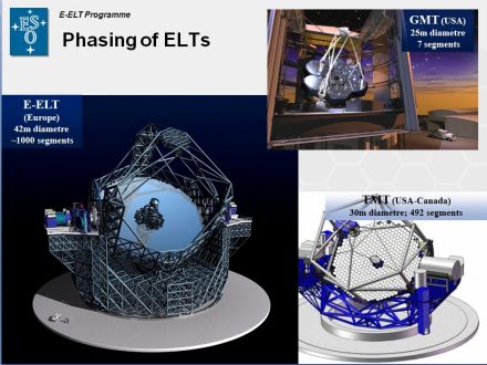
The Active Phasing Experiment (APE) represents a technology evaluation breadboard for large telescopes. The essential purpose of the APE experiment is to explore, integrate, and validate active wavefront control schemes and technologies for a European Giant Optical Telescope (EGOT). This includes the evaluation and comparison of the performance of different types of wavefront sensors in the laboratory and on the sky on the one hand, and the integration of the control of a segmented aperture control into an already existing active system and driving both the active system and the control of the segments on the other hand. APE is close to completion and deployment in an operational environment. APE will be deployed in the lab, standalone, but also in an already existing telescope.
The SE^2 manifesto
Provide the systems engineer the means to state the system problems comprehensively, to ensure that all requirements for a system are satisfied throughout the life cycle of the system, and to develop a model on the basis of which a real system can be built, developed, or deployed (i.e. design a system) (W. Wymore, Model-Based Systems Engineering 1993).
Concrete Goals
- Provide examples of SysML, common modeling problems and approaches
- Build a comprehensive model which serves as the basis for providing different views to different engineering aspects (e.g. system, logical, mechanical, control) and subsequent activities of analysis and design alike.
- Demonstrate that SysML is an effective means to define common concepts (requirement types, interfaces, relationships, etc).
- Demonstrate that a SysML model enhances traceability between requirements, design, and verification/validation.
Why using SysML for APE?
APE, like any complex system, has a large number of functional, performance, physical, and interface requirements which have to be satisfied. This implies the need for professional requirements engineering and management during the project. This is the first application of SysML during development.
APE has about 50 high-level system requirements. The control system has also about 50 requirements, complemented by 150 Use Cases.
APE consists of various elements, like wheels, translation stages, lenses, detectors, (segmented) mirrors, light sources, an interferometer, sensors, and actuators (19 small axes, 10 TCCDs, 11 other devices, 183 actuators for segmented mirror). The control system alone consists of 12 computing nodes. These elements offer all kinds of optical, mechanical, electronic, and software interfaces, both system internal and external to other systems. Their management alone is very challenging for the systems engineering team. Besides these challenges, which apply to many complex systems, APE has some other aspects:
The most noticeable challenge of APE is the highly demanding optical layout, which is a unique challenge for every optical system. The highly sensitive system requires a consistent coordinate system of the various parts to ensure a correct optical path. Apart from this it also challenges the control, since there are several open and closed-loop systems required. A significant amount of data is produced by image processing data flows. Since APE will be deployed in the lab and in an already existing telescope, slightly different functional aspects are active depending on the deployment mode. Therefore different interfaces to existing systems are needed.
We believe that SysML will contribute significantly to tackle these challenges of APE. Another fact about the nature of the project seems important: Being a collaboration of institutes that are geographically distributed, this poses a further challenge on the systems engineering discipline.
Approach
The approach to the problem is primarily top-down. However, some parts of the modeling will be done bottom-up. The approach is a rough guideline and not a solid plan. It will be dynamically adapted if we detect that there is a better way. It's NOT a waterfall approach. Even if the steps described below looks like a waterfall. It's an iterative approach. It's not necessary and not wanted to proceed only with the next step if the previous step is completed.
The model includes at least two abstraction levels throughout analysis and design, without technical solutions and with technical solutions
Describe the objectives of the system and the modeling
- Model elements: Requirements stereotyped with <<objective>>
Determine the requirements
- Break down the requirements if necessary
- Model at least two levels: User and system requirements
- Model elements: SysML requirements and relationships
Describe the context of the system, i.e. its actors
- Model elements: Block stereotyped with <<system>>, actors with stereotypes for categorization purposes, e.g. sensor, actuator
Find the services of the systems, i.e. the use cases
- Model the relationship of the use cases the functional requirements
- Model elements: Use cases and relationships
- Model the use case control and object flows with all important variants and exceptions
- Model elements: activities with all their related elements
Define the domain values and blocks
- Types of blocks used in the use case object flows, units of the domain
- Model elements: Blocks, value types, units, dimensions, relationships
Derive a system design
- At least use two levels, emphasizing technology independent and technology-dependent perspectives as required by the problem statement.
Define the various interfaces among blocks.
- Allocate requirements, use case control and objects flows to system blocks and item flows
- Model elements: Blocks, composition, ports, connectors, item flows, roles
Describe system blocks behavior
- State machines and activity diagrams are used to define physical processes and system behavior
- Model elements: State machines, activity diagrams, and related elements
Describe parametric model
- Model elements: Constraint blocks, Parametric model